IR3100 Infrared BGA Rework Station

IR3100 Infrared BGA Rework Station

The IR 3100 can easily install and remove BGA, QFN, μBGA/CSP, Flip Chip and other SMD's. Featuring a 500W infrared (IR) top heater and a 1000W IR bottom preheater, the IR 3100 does not require nozzles. A specially-developed IR pyrometer provides non-contact, real-time, closed-loop temperature control throughout the reflow process. A Sodr-Cam Reflow Camera comes standard, allowing you to watch the entire reflow process in real time. The IR 3100's newly designed Windows-based software makes profiling incredibly simple for even the most advanced applications, providing intuitive set-up, multi-stage profiling, on-the-fly profile adjustment, flux-dipping, unlimited profile storage and much more.

  • Features
    Non-Contact IR Pyrometer
    Ultra-High Precision Placement Capability
    High Sensitivity Vacuum Pick
    Sodr-Cam Reflow Camera
    Height Adjustable Bottom-Side Preheater
    High-Definition Optical Alignment System
    Quad-Field Imaging for Large/Fine Pitch BGA's
    Integrated Board Support Wand
    Power Distribution Graph
    Sensor Offset
    Made in the USA
  • Specifications
    Power Requirements
    120 VAC, 50/60 Hz (1550 Watts maximum) || 230 VAC, 50 Hz (1550 Watts maximum)
    Dimensions
    737mm (29") H x 686mm (27") W x 737mm (29") D
    Weight (Without Computer)
    45kg (100lbs)
    Top-side Heater
    Medium/Long wave IR, 500 Watts
    Bottom-side Preheater
    Medium/Long wave IR, 1000 Watts; 220mm (8.6”) x 155mm (6.1”)
    Bottom-side Preheater Working Height
    Adjustable working height from lowest position up to 38mm (1.5”) closer to the PCB
    High Sensitivity Vacuum Pick
    Pick is counterweight balanced, and utilizes an optical sensor and precision high temperature linear ball bearings, ensuring delicate placement and pick up of parts from PCB. Includes six (6) Vacuum Picks
    Precision Placement Capability
    Advanced professional placement system utilizing a stepper motor and position encoding provides smooth, precise movement, with no drift, allowing for repeatable and accurate placement.
    Placement Accuracy
    Stepper motor with precision positioning of to 28μm (.0011”) accuracy
    Board Support Capability
    Integrated Board Support Wand prevents PCBs from sagging/warping during rework and is adjustable to clear parts on bottom of PCB
    Maximum Target Temperature
    Each profile zone has a maximum target temperature of 328 °C (624 °F)
    Precision PCB Holder
    Advanced table features micrometer X & Y adjustment, extruded board holder arms, spring loaded, with T-slots and movable clamps for both large and irregularly shaped boards with non-uniform edges
    Maximum/Minimum PCB Size Maximum
    305mm x 305mm (12” x 12”); Minimum: N/A arms close down completely.
    Maximum/Minimum Component Size Maximum
    65mm (2.5”) x 65mm (2.5”); Minimum: 1mm Sq.
    IR Pyrometer and Thermocouple Inputs
    A specially developed IR sensor provides non-contact, real-time, closed-loop temperature control throughout the reflow process. In addition, four (4) thermocouple inputs provide additional real-time monitoring (includes 2 K-type thermocouples)
    High Definition Optical Alignment System
    Vision Overlay System (VOS) with High Definition (1080p) color camera, integrated frame grabber, dichroic beam-splitting prism, independently controlled LED illumination for component and PCB. Up to 240x zoom capability and Stable Zoom.
    Motorized Optics Housing (Sodr-Cam
    Allows the developer to watch the entire reflow process in real time to verify solder melt. The camera arm rotates to provide a 180-degree view at a fixed distance, for minimal focus adjustment and ease of use.
    Quad-Field Imaging
    For large component alignment (including fine-pitch QFPs), allows up to four opposite corners of a large component (and its pads) to be viewed under higher magnification
    Single Axis Operation
    All operations, including component pick-up, alignment, placement, reflow & active cooling are completed in a single axis, eliminating risk of component movement after placement and reflow.
    Auxiliary Cooling Fan
    Standard, for secondary cooling of the PCB
    Component Nests
    Two (2) removable and adjustable Component Nests provided for perfect centering of components, in preparation for vacuum pick-up/placement. Optional component holding system for parts under 5mm Sq.
    Flux Dip Plate
    Included; allows for automated flux dipping
    Stencils/Solder Paste
    Over 145 stencil kits are optionally available (requires Universal Bracket Kit) and are integrated into the installation process
  • More Information


    Advanced Features

    sadf


    Ultra-High Precision Placement Capability: Motorized reflow head is driven by advanced stepper motor system providing smooth, high precision, repeatable movement with no drift, allowing for soft landing of components and 28μm (.0011") placement accuracy. 
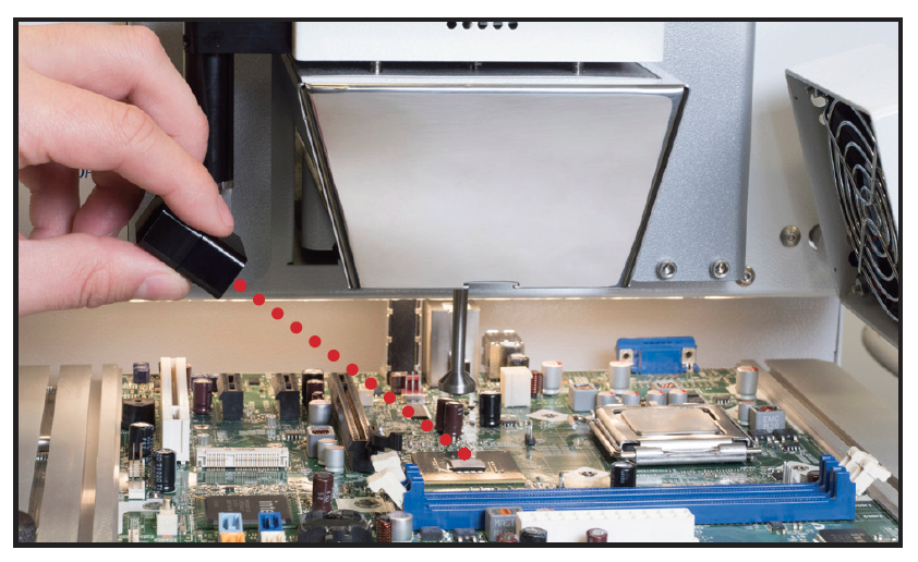
    High Sensitivity Vacuum Pick: New Vacuum Pick design is more robust, utilizes an optical sensor, is counterweight balanced, and employs precision high-temperature linear ball bearings for maximum accuracy and sensitivity in placement and pick-up. 
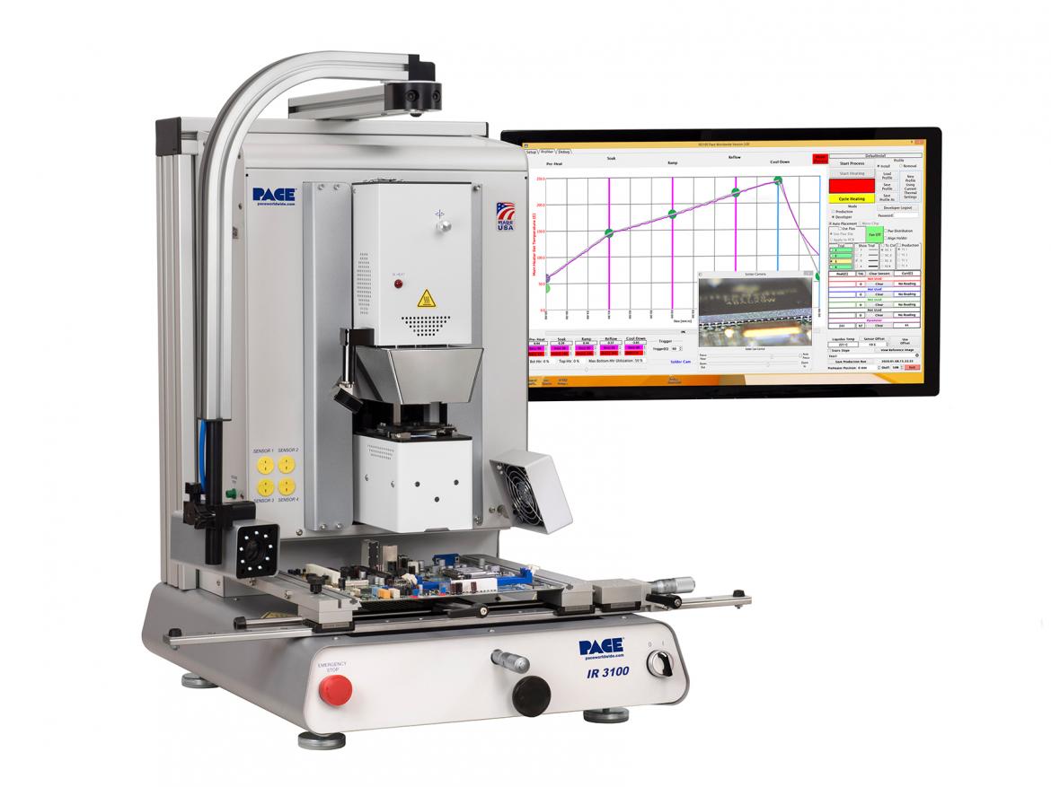
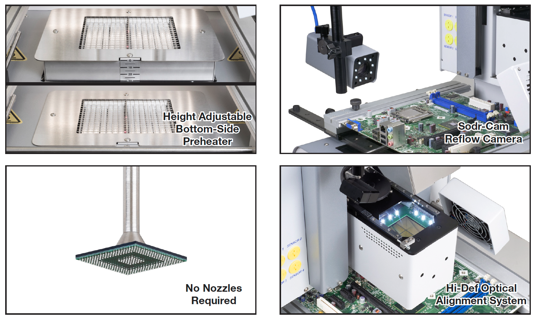
    Sodr-Cam Reflow Camera: Provided Sodr-Cam allows the operator to verify the entire reflow process, including the exact moment of solder melt. 

    Height Adjustable Bottom-Side Preheater: High powered (1000W) IR preheater height is adjustable from standard position up to 38mm (1.5") closer to the PCB for the most challenging high-thermal -mass boards. 

    High-Definition Optical Alignment System: Automated Vision Overlay System uses a beam-splitting prism, high intensity LEDs for shadow-free lighting and a new high definition 1080p camera for easy alignment. 

    Quad-Field Imaging for Large/Fine Pitch BGA's: Allows up to four corners of a large component (and its lands) to be viewed under high magnification, providing perfect alignment of outsized BGAs or fine-pitch QFPs. 

    Integrated Board Support Wand: Prevents warping or sagging during reflow, is extremely adjustable to clear parts on the bottom of PCB and is easily removed when not in use. 

    Power Distribution Graph: Provides a graphical analysis of the top heater output within each zone, helping the developer make necessary adjustments to either the bottom heater utilization, or ramp rate, to maximize thermal performance. 

    Sensor Offset: Allows the developer to easily match the pyrometer temperature reading to the actual solder temperature.

    ir pyrometer


    Non-Contact IR Pyrometer: A closed-loop, non-contact IR pyrometer monitors and controls the ramp-rate and temperature of the component in real time, by controlling the top and bottom heaters’ output throughout the heating process.


  • Resources
  • Manuals
    Sodr-Cam Installation Guide
    IR3100 & IR4100 Manual
  • Brochures
    IR3100 Info & Spec Sheet 2020
  • Additional Videos